logo
Good price  online

products details

Created with Pixso. Home Created with Pixso. Products Created with Pixso.
Semiconductor Equipment
Created with Pixso. Precision Multi-Wire Saw for Semiconductor Wafer Cutting and Thin Slicing

Precision Multi-Wire Saw for Semiconductor Wafer Cutting and Thin Slicing

Detail Information
Product Description

Precision Multi-Wire Saw for Semiconductor Wafer Cutting and Thin Slicing

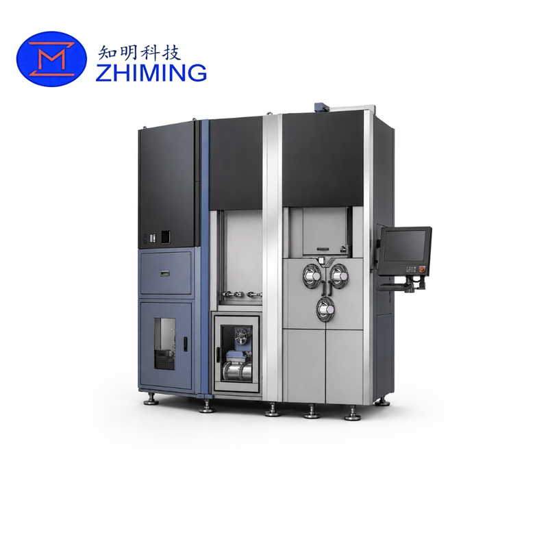
The Precision Multi-Wire Saw for Semiconductor Wafer Cutting is an industrial slicing system developed for applications requiring controlled wire motion, stable tension, precision feed, thin-section cutting and consistent machine rigidity.

The equipment integrates wire supply and take-up, wire traversing, tension control, guide wheels, main roller drive, workpiece feeding, slurry circulation, heat exchange and electrical control into a single machine platform. The supplied equipment documentation identifies its intended industry application as semiconductor wafer slicing.

With a maximum specified wire speed of 2200 m/min, a supported wire diameter range of 0.014–0.10 mm, adjustable tension from 0 to 15 N, and variable cutting feed from 0.01 to 5 mm/min, the system provides a flexible platform for fine-wire wafer slicing processes.

This machine can be considered for semiconductor production lines, pilot production, material processing facilities and research environments where slicing accuracy, wire stability and equipment repeatability are important.

Main Advantages

High-Speed Wire Operation

The machine supports a maximum wire speed of:

2200 m/min

High wire speed is especially important when finer wire is used, because cutting force and process stability must still be maintained as the wire diameter decreases.

The available wire diameter range is:

0.014 mm to 0.10 mm

This allows users to select wire specifications according to the target slicing process.

Adjustable Wire Tension

Wire tension can be controlled from:

0–15 N

The tension arm is used to maintain the steel wire at the selected tension during operation. According to the machine configuration, the tension control system is motor driven and can be adjusted according to process requirements.

Stable tension is one of the key mechanical conditions for maintaining predictable wire movement during wafer slicing.

Precision Feed Control

The machine uses a controlled feed unit with a maximum travel of approximately:

220 mm

Cutting feed speed:

0.01–5 mm/min

Rapid feed speed:

200 mm/min

The workpiece is fixed to the feed unit and moved through the cutting area according to the selected process parameters.

Processing Capacity

The standard processing envelope specified for the equipment is:

Parameter Specification
Maximum Workpiece Size W90 × H220 × L450 mm
Maximum Workpiece Length 450 mm
Feed Travel ≤220 mm
Workpiece Clamping Automatic hydraulic clamping
Cutting Direction Downward feed
Wire Movement Reciprocating / Unidirectional

The system also supports combined workpiece loading according to the original technical configuration.

Technical Specifications

Item Specification
Maximum Wire Speed 2200 m/min
Wire Diameter 0.014–0.10 mm
Maximum Wire Storage 100 km
Wire Tension 0–15 N
Feed Stroke ≤220 mm
Cutting Feed Speed 0.01–5 mm/min
Rapid Feed 200 mm/min
Main Roller Speed <4500 r/min
Main Roller Maximum Diameter Ø160 mm
Main Roller Quantity 3 pcs + 3 spare
Slurry Tank Capacity 300 L
Workpiece Clamping Automatic hydraulic
Wire Break Detection Included
Standard Power Supply AC 380 V ±10%, 50/60 Hz
Machine Dimensions Approx. L1750 × W1600 × H2900 mm
Machine Weight Approx. 8 tons

These parameters are taken from the supplied equipment configuration.

Integrated Wire Management System

The machine includes several coordinated subsystems responsible for controlling wire movement.

Wire Winding Unit

The winding unit holds the new wire spool and receiving spool. It is responsible for supplying and storing the steel wire during machine operation.

Wire Traversing Unit

The traversing mechanism helps the wire unwind smoothly and rewind evenly.

Tension Arm

The tension unit maintains the wire at a controlled tension during slicing.

Guide Wheels

Guide wheels are used to direct the wire and support stable wire travel.

Main Spindle Unit

The main spindle section performs the actual slicing operation between the rollers.

Feed Unit

The workpiece is secured to the feed system and moved at a programmed speed during cutting.

These units are described as the main components of the overall machine system.

Slurry and Cooling System

The cutting machine is equipped with a slurry circulation system with a tank capacity of:

300 L

The slurry tank provides cooling and cutting fluid during processing.

A heat exchanger is used to control cutting-liquid temperature through external cooling water. The specified cooling-water requirements include:

Cooling Parameter Requirement
Water Temperature 11 ±1°C
Water Flow 20–50 L/min
Water Pressure 0.2–0.4 MPa
Cooling Capacity ≥5 kW

The cooling-water circuit uses insulation to reduce condensation.

Rigid Machine Structure

The machine enclosure uses a high-strength steel structure, while the base uses an integrated cast construction to improve overall rigidity.

The equipment is also designed with a tray underneath the machine to reduce the possibility of cutting liquid leaking directly onto the installation floor.

A pneumatic safety device is installed at the upper section of the equipment to improve the safety and stability of the lifting platform.

Direct-Drive Architecture

The drive system uses direct coupling.

According to the supplied equipment specification, the main benefits of the direct-drive structure include:

  • Lower operating noise
  • Reduced wear-part consumption
  • Higher drive precision

The main rollers are also individually motor driven. This design is intended to reduce the load transferred from the wire to the rollers and reduce roller groove wear and wire consumption.

Compact Roller Spacing

The documented roller-axis spacing is approximately:

270 mm

The shorter spacing is designed to reduce the distance between the main rollers and thereby improve cutting conditions.

According to the original technical documentation, this design is intended to improve cutting yield while reducing processing time and wire consumption.

Wire Break Monitoring

Wire breakage is an important process risk during wafer slicing.

The equipment includes wire break detection as part of its standard technical configuration.

The machine also uses dual-side break alarm monitoring to improve break-detection sensitivity. Its control system incorporates protection intended to reduce wire breakage during unexpected power interruption.

Mechanical Accuracy

The machine acceptance specification includes several important mechanical inspection parameters:

Inspection Parameter Requirement
Main Roller Runout ≤0.02 mm
Spindle Box Taper Radial Runout ≤0.005 mm
Spindle Core Axial Runout ≤0.005 mm
Taper Contact Ratio ≥70%
Vertical Feed Straightness ≤0.005 mm / 150 mm
Wire Twist <5 turns / m
Supply/Take-Up Spindle Vibration ≤5 m/s²
Supply/Take-Up Roller Runout ≤0.15 mm

These values define the documented machine-level acceptance requirements.

Thin Wafer Cutting Capability

The equipment documentation states:

Cutting accuracy: ±0.01 mm

and

Minimum slicing thickness: <0.05 mm

The exact achievable thickness in production will depend on the workpiece, wire specification, process recipe, cutting fluid, handling method and required yield.

For very thin wafer projects, customers should provide the target thickness and tolerance before equipment configuration is finalized.

Electrical and Facility Requirements

Standard machine power:

Three-phase four-wire AC 380 V ±10%, 50/60 Hz

The technical documentation specifies the installation of copper cable of 16 mm² or above.

The referenced machine energy consumption is approximately:

5 kWh

Actual consumption can vary with operating conditions and auxiliary systems.

Recommended Installation Environment

Recommended environmental conditions include:

Item Requirement
Ambient Temperature 18–28°C
Relative Humidity ≤75%
Vibration ≤0.5 G

The machine specification also confirms support for a maximum wire storage capacity above 100 km when using Ø0.03 mm wire, six guide wheels, a 300 L slurry tank and hydraulic workpiece clamping.

Application

The documented application of this equipment is:

Semiconductor Wafer Slicing.

Typical customer projects may involve different wafer diameters, target thicknesses and production requirements.

Because cutting behavior varies significantly by material, customers planning to process different semiconductor or hard-brittle materials should provide the material information to ZMSH for process evaluation before confirming the final machine configuration.

Precision Multi-Wire Saw for Semiconductor Wafer Cutting and Thin Slicing

Custom Equipment Configuration

Different semiconductor wafer projects can require different:

  • Wire diameter
  • Wire tension
  • Feed speed
  • Workpiece fixture
  • Cooling conditions
  • Slurry configuration
  • Communication interface
  • Production capacity

Optional configurations listed in the equipment documentation include SECS II communication, cooling equipment and workpiece clamping temperature control.

ZMSH can therefore evaluate equipment configuration according to the customer's process requirements.

RFQ Information

Precision Multi-Wire Saw for Semiconductor Wafer Cutting and Thin Slicing

For a quotation or technical evaluation, please provide:

  1. Material
  2. Workpiece dimensions
  3. Required wafer dimensions
  4. Target wafer thickness
  5. Thickness tolerance
  6. Quantity per batch
  7. Monthly or daily capacity
  8. Wire specification, if already defined
  9. Required cutting accuracy
  10. Cooling-water conditions
  11. Factory power supply
  12. Required optional functions

Providing these details helps determine the appropriate machine and process configuration.

FAQ

What is the maximum cutting wire speed?

The maximum specified wire speed is 2200 m/min.

What wire diameter can the machine use?

The specified wire diameter range is 0.014–0.10 mm.

How thin can the machine slice?

The equipment documentation states that slicing thicknesses below 0.05 mm are possible under the relevant operating conditions.